Blog
Home
This is the work I have done as part of my undergraduate thesis at the Computer Science department of IIT Madras, under the guidance of Prof. Chester Rebeiro, CSE Dept, IIT Madras. The primary motives of this project are two-fold:
- Build a webserver that interacts directly with the hardware and requires minimal interaction with kernel for its execution.
- Use Rust as the language – Rust, by its design, produces memory-safe applications and therefore is an ideal language to write servers on the cloud.
All the source code regarding this project is available here:
Both the above repositories are almost identical.
Drop me an email if you’d like to learn more.
Packet Exchange Demo
Here’s the link for the packet exchange demo. Will try to embed it into this page at a later stage. Demo Link!
Pay the Piper
For a long time, servers on the cloud were being written in C or C++. Being low-level languages, they have the advantage of speed over applications written in higher-level languages like Java or Python. However, this definitive advantage comes with a small glitch - Applications written in these languages are prone to memory errors in the form of segmentation faults, dangling pointers etc., resulting in crashes. In this regard, there is a need for a language that guarantees the memory safety and be capable of doing it without compromising on speed.
Enter Rust!
Rust
Rust is a systems programming language that is focused on safety, security and concurrency. Rust has almost zero run-time. All the type checking is done during the compile time which leaves very less to be done during the runtime, thereby ensuring the speed. As for the safety, features like Ownership__, __References & Borrowing, and Lifetimes give it a superior memory management scheme that is devoid of memory errors. Therefore Rust is fast as well as memory safe, which is exactly the kind of language we are looking for and therefore is a better alternative for writing low-level, performance-critical applications like device drivers or operating systems. This also works well in the cloud. Our aim here is to write a server that will run on an Unikernel which can inturn be hosted on a bare-metal hardware on the cloud.
You can read more about Rust and its superior features here.
Unikernel
Unikernel is a single address space machine. It could be seen as a miniature Operating System which can run just one program. Basically, it is just a subset of OS libraries that we need and compiled into a bootable image. The Unikernel in our project servers two purposes:
- Provide an execution environment.
- Memory Management through Paging and Interrupt Service Routines.
It boots and starts the server and helps it during the packet transmission and reception mechanisms by providing the Interrupt Service Routines. (ISRs)
How do we proceed?
Well, that might be a lot to take especially if you are a begineer. But trust me, I was also a beginner when I got started with it and had almost zero knowledge of how to proceed. However, numerous google searches and a lot of research on IRC forums, I landed up with a roadmap. Although, the path after this was marked by segmentation faults and stupidities and ignorance of an amateur. I won’t be talking about them here, but it just feels good to acknowledge them. After all, we learn from our mistakes, right?
-
To start with, first we need to build an Unikernel. For our project we just need a basic unikernel, which boots and calls the server’s main code. Therefore it will ease our process by a bit. Fortunately we already have a fantastic series of blog posts written by Phillip Oppermann. I used the OS he built as my Unikernel, with some slight modifications.
-
Next, we will boot this OS on a hypervisor (Qemu). Once that setup is working, we need to detect the underlying hardware, especially the network device which will be our bridge between the physical layer and the application layer.
-
Once we detect the network device we write the device driver for the ethernet card. This involves writing the packet Transmission and Reception mechanisms.
-
Include a file system, threads and write a basic server-client handshake protocol and the project is done.
Detecting the hardware devices
Hardware devices are connected to the CPU through a device called the PCI bus. PCI stands for Peripheral Component Interconnect. There are a total of 256 buses in this device. The first bus is called the Primary bus and the rest are called secondary buses. They are connected to each other by a PCI-PCI bridge. Each of these buses contain 32 pins and each pin coresspond to a hardware device.
Each PCI device is characterized by the following features: - Vendor ID - Device ID - Register number - Function number
A PCI device could be anything ranging from a VGA card, Ethernet Network
Controller to a Sound card, a mouse or a keyboard. Now we need to figure
out a way to communicate with these PCI devices. There are two ways to
do this… ### Ports I/O In this method, there exists a special I/O
address space away from the RAM and an IO pin is enabled each time an
I/O query happens. Looking at this the CPU diverts the query to this
address space. Device address spaces are embedded into this. They are
accessed as base_address + io_offset using special offsets called
Ports. ### Memory Mapped I/O In this method the device address spaces
are embedded in the RAM itself and we just need to know where they are
situated in order to access them.
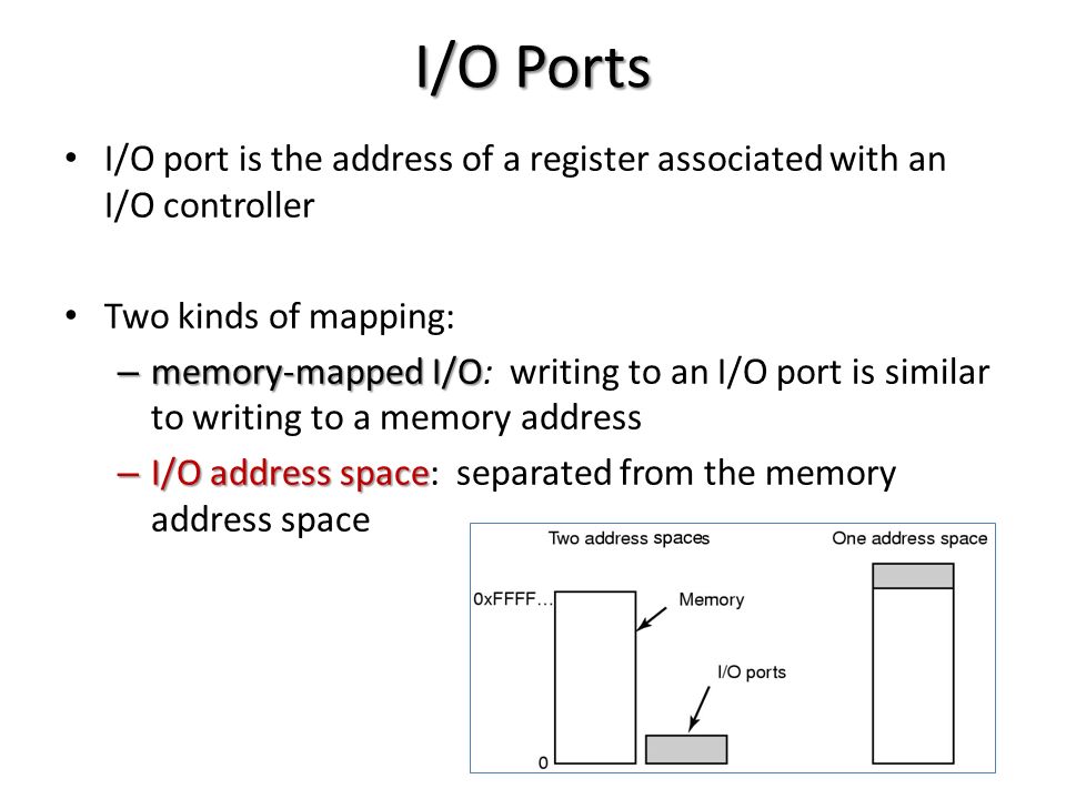
To know more about the distinction read this. We will be using Memory Mapped I/O in our project.
Each PCI device consists of two ports/offsets within the device namely
address_port and data_port which can be used to communicate with and
get information about the device. See the code below.
pub struct Pci {
  address_port: Port,
  data_port: Port
}

impl Pci {
  pub fn new() -> Pci {
    let address_port = Port::new(0xcf8);
    let data_port = Port::new(0xcfc);
    Pci { address_port: address_port, data_port: data_port }
  }
}
Each of these ports are 32-bit numbers and can be read and written to. A
port can be thought of as an offset within the device. For more
information regarding this refer OS Dev Wiki :
PCI. Read
this
and
this.
Now we query the address port of a PCI device by building the I/O
address for each device given the device number and bus number. This
query will output the information about vendorID, deviceID etc.., of the
device into the data port of the device. Let’s go step-by-step.
The below code snippet will build the address to be queried in the I/O address space we discussed earlier. As we can see the device number cannot be greater than 31. Now we build the I/O address. The 32nd MSB will be 1, indicates that the address query should go to I/O space. The first 16 bits correspond to the bus number, next 5 bits belong to the device number, next 3 bits correspond to the function number and the remaining bits are offset bits.
impl Pci {

  pub fn new() -> Pci {
    let address_port = Port::new(0xcf8);
    let data_port = Port::new(0xcfc);
    Pci { address_port: address_port, data_port: data_port }
  }

  fn build_address(bus: u8, device: u8, function: u8, offset: u8) -> u32 {
    if (function & 0x03 != 0x00) || (device >= 0x1 << 5) || (function >= 0x1 << 3)  {
      panic!()
    } else {
      return ((0x1 as u32) << 31) | ((bus as u32) << 16) | ((device as u32) << 11) | ((function as u32) << 8) | offset as u32;
    }
  }
Once we build the address, we put this into the address port of the PCI device and it returns a 32-bit memory block that starts at the input address into the data port.
 pub fn read(
   self, bus: u8, device: u8, function: u8, offset: u8) -> Result<u32, ()> {
   let address = Pci::build_address(bus, device, function, offset);

       // The below three steps are standard procedure for probing s PCI device.
   self.address_port.out32(address);
   Port::io_wait();
   let input = self.data_port.in32();
   Ok(input)
 }
Using the above preliminary function repeatedly, we can read all about the device, 4 bytes at a time.
  pub fn read_bytes(&mut self, bus: u8, device: u8, start_address: u16, size: u16) -> Vec<u32> {
    assert_eq!(size % 4, 0);
    assert_eq!(start_address % 4, 0);

    let mut v = Vec::new();
    for i in 0_u16..(size / 4) {
      let (offset, function): (u8, u8) = unsafe { transmute((start_address + i*4) as u16) };
      v.push(self.read(bus, device, function, offset).unwrap());
    }
    v
  }

  fn read_as<T>(&mut self, bus: u8, device: u8, start_address: u16) -> Box<T> {
    let v = self.read_bytes(bus, device, start_address, size_of::<T>() as u16);
    let slice = &v[..];
    let read = read_into(slice);
    return read;
  }

  fn read_header(&mut self, bus: u8, device: u8) -> Option<PciHeader> {
    let (vendor, _): (u16, u16) = unsafe { transmute(self.read(bus, device, 0, 0).unwrap()) };

    // This is an invalid vendor code. Output when no device exists on that bus.
    if vendor == 0xffff {
      return None
    }

    let shared: SharedHeader = *self.read_as(bus, device, 0);
    //println!("{:?}", shared.header_type);
    let rest = match shared.header_type {
      0x00 => HeaderType::Basic(*self.read_as(bus, device, size_of::<SharedHeader>() as u16)),
      0x01 => HeaderType::Todo,
      0x02 => HeaderType::Todo,
      _ => {
        //println!("weird header");
        return None
      }
    };

    Some(PciHeader { shared: shared, rest: rest })
  }

}
This is the main program. It extracts the device information from the
devices in all the 256 buses and checks which are valid and which are
not. Looking at the class and sub-class information of each device, we
identify that the address space concerns the corresponding hardware
device. Specifically we are looking for the Ethernet Adapter Controller.
Its class number is 0x02 and sub-class is 0x00. Here’s the list of
devices that we found.
impl DriverManager for Pci {

  fn get_drivers(&mut self) -> Vec<Box<NetworkDriver + 'static>> {
    let mut no_device_count: usize = 0;
    let mut device_count: usize = 0;

    let mut io_offset: u32 = 0;
    for bus in 0..255usize {
      for device in 0..32usize {

        //println!("{:?}...{:?}", bus,device);
        match self.read_header(bus as u8, device as u8) {
          None => no_device_count += 1,
          Some(header) => {

            device_count += 1;
            let shared = header.shared;
            // println!("bus #{} found device 0x{:x} -- vendor 0x{:x}", bus, shared.device, shared.vendor);
            // print!("    class 0x{:x}, subclass 0x{:x}", shared.class_code, shared.subclass);
            // print!("    header type 0x{:x}", shared.header_type);
            // print!("    status 0x{:x}, command 0x{:x}", shared.status, shared.command);

            match header.rest {
              HeaderType::Basic(next) => {

                if (shared.vendor == 0x10ec) && (shared.device == 0x8139 ) {
                  io_offset = (next.base_addresses[0] >> 2) << 2 ;
                  self.address_port.out32(Pci::build_address(bus as u8, device as u8, 0, 4)) ;
                  self.data_port.out16(shared.command | 0x4) ;
                  if io_offset != 0 {
                    let manifest = Rtl8139::manifest();
                    let granter = PortGranter { base: io_offset as usize, limit: manifest.register_limit as usize };
                  }
                }

              }
              _ => ()
            }
          }
        }
      }
    }

    let mut ret: Vec<Box<NetworkDriver>> = Vec::new() ;
    ret
  }

}
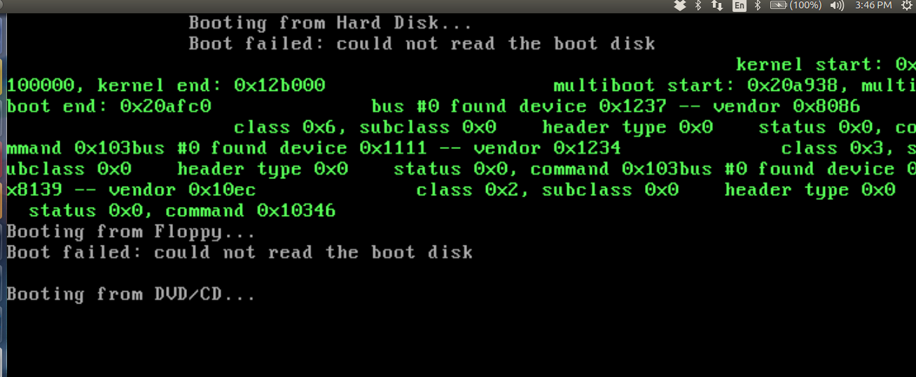
Sorry for bad formatting but if you look closely, we can find a device
with deviceID-0x8139, vendorID-0x10EC,class-0x02 and
subclass-0x00. We need to find out what the device is. So, fire up the
browser. O Wait! You are already in the browser! Anyways, go to this
site http://pcidatabase.com/ and enter the vendorID and deviceID in
them. You will find the following output.
0x8139 RTL8139 Fast Ethernet NIC 0x10EC Realtek Semiconductor Corp.
So it is the infamous RTL8139 Ethernet Network Interface Controller.
Hurray! We have found the network card. Let’s figure out how we can talk
with it?
Incase you are emulating the hardware using a Virtual Machine like Qemu for testing, you need to setup the ethernet card configuration before hand. There are several Network cards that Qemu supports. Fortunately it supports RTL8139 card. We set it using the following command.
qemu-system-x86_64 -hda /path/to/hda.img -netdev user,id=user.0 -device rtl8139,netdev=user.0
By default, the network device will be set to e1000 in Qemu.
Ethernet Driver Development for RTL8139
Driver development is so complicated as it involves frequent communication with the hardware addresses and ports. However there is a smooth road map that one can follow to write a network device driver. They are as follows:
- Detecting the device
- Enabling the device
- Understanding the device
- Initializing the device
- Transmission Mechanism
- Transmitting the Packets
- Receiving Mechanism
- Receiving the Packets
Detecting the device
This is already done this using the probe method we described above. The
discov- ered device will have a device id of 0x8139 and vendor id
0x10EC.
Enabling the device
The command register of the network card exists at an offset of 0x37.
By writing into this offset, we can send commands to the card. Using
this we enable the transmission and receiving capabilities of the card.
Understanding the device
The RTL8139 consists of many components. A thorough understanding of what each device does is important for writing a driver to it. Lets see what each field does : - Name: Contains the name of the device, something like eth0 etc., - Base address: Contains the I/O base address of the device. - Device address: Hardware MAC address of the device. - Broadcast: Device’s broadcast address - Hardware header Length: The number of bytes that lead the packet before the IP header. Typically this length is 14 for an ethernet header. - IRQ: It is the interrupt number that our device is assigned. - Open fn: This is a pointer to the function that opens the device. This function can register any system resource it needs like I/O ports, DMA, IRQ etc.., and should be able to turn on the hardware, increment the count etc.., - Transmit fn: Puts the packet on the wire.
There is no member function to receive the packets. This is done by the device interrupt handler, which we will see later.
Initializing the device
Initializing the device involves resetting all the values in the I/O port offsets to their defaults. In this process, we configure the transmit buffer, receive buffer, set their start addresses and enable all the interrupts.
Transmission Mechanism
RTL8139 allocates four ports internally for the sake of transmission.
These ports are located at an offset of 0x20,0x24,0x28,0x2C from
the device’s base address. According to the RTL8139 specification these
ports are called Transmit Start Ad- dress Descriptors and are named as
TSAD0, TSAD1, TSAD2 and TSAD3. These descriptors transmit the packets in
a round-robin manner. If descriptor0 is used to transmit the current
packet then descriptor1 will be used to transmit the next packet. As the
name suggests these descriptors store the start addresses of the packet
to be transmitted. Once we write this address and the length of the
packet into the ports the device will perform a **DMA **(Direct Memory
Access) to this address, gets the packet and transmits it.
Transmitting the Packets
Transmitting the packets is relatively easier when compared to receiving. First we enable the transmit flag of the device. After that we put the address of the packet to be transmitted into one of the TSADs. The device reads the corresponding address through DMA and puts it on the wire. Packet is transmitted. Here is the code that shows all the above said procedure.
fn put_frame(&mut self, buf: &[u8]) -> Result<usize, u32> {
  self.transmit_address[self.descriptor].out32(buf.as_ptr() as u32);
  self.transmit_status[self.descriptor].out32(0xfff & (buf.len() as u32));
  while (self.transmit_status[self.descriptor].in32() & 0x8000) == 0 {
  }
  self.descriptor = (self.descriptor + 1) % 4 ;
  Ok(buf.len())
}
&mut self is the mutable reference to the Network driver. The packet
that needs to be transferred will be in the buf slice. In the first step
we write the virtual address of the packet to one of the Transmit Start
Address Descriptor and we put the length it should read into the
Transmit -Status Descriptor. Once these two steps are done, the device
performs DMA in the background and once the DMA is completed, it updates
the Transmit Status Descriptor with the TxOK macro. Once we find it,
we increment the to-be-used descriptor for the next packet to be
transmitted.
Receiving Mechanism
The receive path of the packets is designed as a ring buffer. Whenever the device receives packets, the contents are stored in the ring buffer and the address at which the next packet is to be stored is updated. Once the linear memory for the buffer is completely exhausted, it again starts storing from the top.
Receiving the Packets
(Will write a more detailed explanation when cometh the time.)
Whenever a packet is received, the device generates a hardware interrupt with an interrupt number and transfers it to the PIC. PIC stands for Programmable Interrupt Controller which manages the entire system interrupts. Since the first 32 interrupts are reserved for Software exceptions, our hardware IRQ1 must somehow be re-assigned to some other number. To achieve this PIC will have a built-in offset to the IRQ it receives. It adds this to the IRQ number and generates a software interrupt with the final number and sends it to the IDT. IDT then stops everything, saves the context to the stack, jumps into the ISR and use the kernel stack for servicing the interrupt. In ISR we decide on how to handle the received packet.
All credits to OS Dev Wiki! and my OS course.
Testing
For testing first we need to setup a network backend and establish
connection between the devices. Then we can use this network to exchange
the packets and get the network activity. We use the dump configuration
of the -net option of qemu to monitor the network traffic. This
essentially catches any packets that were being transmitted over the
network and dumps them into a file. We can retrieve the contents of this
file using the tcpdump command.
Setting up a Network
There are many ways of setting up the network backend, however there are two main methods that we can use to test our transmission and receiving mechanism. They are as follows
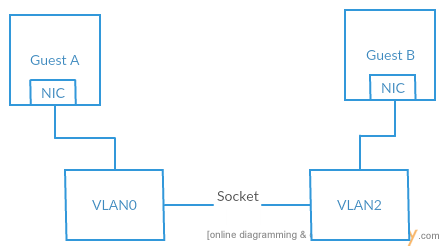
Connecting VLANs together
We simulate two different instances of our kernel, one containing the code for receiving and the other for receiving. Each guest OS is connected to its corre- sponding VLAN. In this configuration all the packets that were transmitted by the guest will be received by all the devices in that VLAN. So, if we can connect both the VLANs together using a socket, we will be able to communicate between the two guest OSes. To achieve this, we choose a port and make one OS to listen to itand the other port to connect to it. Following figure depicts the connection that is established between two virtual machines.
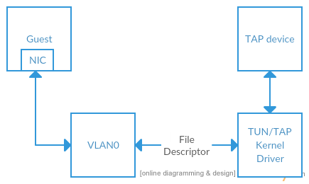
Connecting VLAN to a TAP device
Another option is making the VLAN available from the host OS. Frames transmit- ted by the TAP device on the host OS appear on the VLAN of qemu and vice versa. If this TAP device is assigned as an IP address applications in the guest will be able to connect to the host listening for connections on that IP address. Port forwarding can be used to connect the guest OS to internet. Essentially a TAP device works as a snooper for the communications in between the guest OS and the internet.
Testing Code
pub fn test(&mut self) -> Result<(), EndOfFile> {
  //self.card.listen();
  let address = self.card.address();
  let source = address;
  let destination = [0xff, 0xff, 0xff, 0xff, 0xff, 0xff] ;
  let raw = [b’u’, b’d’, b’p’, b’!’];
  let u_header = UdpHeader::new(10, 10, raw.len() as u16);
  //192.168.100.2 & 192.168.100.1 ==>  40151232,23374016
  let i_header = IpHeader::new((raw.len() + size_of:: <UdpHeader>()) as u16, 0x11, 40151232,23374016);
  let header = EthernetHeader::new(source, destination, 0x0800);
  let to_send = &(header, i_header, u_header,raw) ;
  adap_ref(&mut*self.card).write(unsafe { transmute((to_send, size_of::<(EthernetHeader, IpHeader,
  UdpHeader)>() + raw.len())) }).ok();
  Ok(())
}
During testing, we build a raw packet with data as ”udp!” and introduce
Ethernet Header and IP Header on top of it. In the ethernet header,
source address is set as the device’s MAC address and the destination is
set as 255.255.255.255.255.255 which is the broadcast address for the
given device. On transmission the packet will be sent to all the other
devices connected to our device in this network.
Results
We configure qemu so that all the network traffic will be dumped into
the file /tmp/vm0.pcap. Later to check the transmission, this file can
be read using either tcpdump or wireshark. Below is an output of the
tcpdump after transmitting a packet. The length is equal to 4 because
the raw data in the above packet is ”udp!” and its length is 4. So,
transmission was successful.
Output
reading from file /tmp/vm0.pcap, link-type EN10MB (Ethernet)
06:38:12.763369 IP truncated-ip - 5100 bytes missing!
192.168.100.2.10 > 192.168.100.1.10: UDP, length 4
The output shows that a packet is getting transmitted from an IP address
192.168.100.2 which is the guest OS’s IP address to 192.168.100.1
which is the default address of the TAP device. A more complicated setup
is required to demonstrate the reception mechanism. We will keep it for
the future.
TODO
I was unable to implement the Reception Mechanism as I couldn’t get the driver to send an interrupt to the IDT.(Completed)Once the above problem is dealt with, we can handle the reception mechanism.(Completed. Look at the demo link at the top of the page.)- Once that is done, we should think about the kind of server we are trying to implement - FTP, HTTP, UDP etc..,
- I guess we need an explicit File System and Threads to be enabled in our Unikernel to process user requests.
- Code the server.
Now, Try NOT to imagine a pink elephant sitting in a beach wearing shades and drinking a coconut under an umbrella.
You just did. Cheers!
Rajiv